
1. Background
The virtual IPI delivery requires two VM exits: one on the sending core to virtualize the MMIO APIC write (xAPIC) / MSR write (x2APIC) and send a real IPI, and one on the destination core to handle the real IPI and inject the interrupt into the guest OS. However, people may want to eliminate VM exits in some performance critical systems to avoid performance degradation.
There are two existing methods to virtualize IPIs with just one VM exit on the sending core and no VM exits on the receiving core. The first method is to configure Pin-Based VM-Execution Controls field to directly avoid VM exit when receiving interrupts. The other one is to use posted-interrupt processing technology.
It is also possible for the guest OS to send virtual IPIs without a VM exit on the sending core, such as by giving the guest OS direct access to the APIC’s registers. However, this is unsafe in current x86 architecture as it would enable the guest OS to send arbitrary interrupt vectors to any core in the system.
We need a safe hardware-assisted method to eliminate the VM exit on the sending core without security problem described above.
2. A safe Hardware-assisted method for IPI Virtualization
This post proposes a new concept called VMCS Class and use it to avoid potential security issues when sending virtual IPIs without a VM exit. This is a safe hardware-assisted method to eliminate the VM exit on the sending core which can be adopted by some performance critical systems.
VMCS Class Table (VCT):
The VMCS Class Table contains a set of VMCS which belongs to the same class. The layout for the VMCS Class Table has following format:
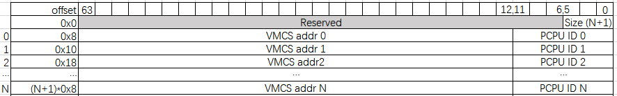
Table 1 VMCS Class Table format
VMCS Class Table Pointer (VCTP):
The VMCS Class Table Pointer (VCTP) is a new VM-Execution Control Field contains the address of the VMCS Class Table associated with this VMCS. VMCS Class Table is transparent to guests.
Secondary Processor-Based VM-Execution Controls (bit 29) – Safe virtual IPI issuing
This control enables the safe virtual IPI issuing without VM exit.
Safe Virtual IPI Issuing without VM exit
xAPIC
A write access to the APIC-access page (Page offset is 300H)
If following conditions are all true:
- “virtual-interrupt delivery” VM-execution control is 1.
- “safe virtual IPI issuing” VM-execution control is 1.
- Reserved bits (31:20, 17:16, 13) and bit 12 (delivery status) are all 0.
- Bits 19:18 (destination shorthand) are 00B (No Shorthand).
- Bit 15 (trigger mode) is 0 (edge).
- Bits 10:8 (delivery mode) are 000B (fixed).
- Bits 11 (destination mode) are 0 or 1 (Physical or Logical).
- Bits 7:4 (the upper half of the vector) are not 0000B.
Then:
- The processor virtualizes a write access to the APIC-access page by writing data to the corresponding page offset on the virtual-APIC page.
- Determining IPI Destination vCPUs by following the standard LAPIC protocol. If the destination vCPUs are all located in the VCT, then send the real IPI to the corresponding pCPUs; otherwise inject a #GP(0) to the guest.
x2APIC
WRMSR in non-root mode (ECX contains 830H)
If following conditions are all true:
- “virtualize x2APIC mode” VM-execution control is 1.
- “virtual-interrupt delivery” VM-execution control is 1.
- “safe virtual IPI issuing” VM-execution control is 1.
- Reserved bits (31:20, 17:16, 13:12) are all 0.
- Bits 19:18 (destination shorthand) are 00B (No Shorthand).
- Bit 15 (trigger mode) is 0 (edge).
- Bits 10:8 (delivery mode) are 000B (fixed).
- Bits 11 (destination mode) are 0 or 1 (Physical or Logical).
- Bits 7:4 (the upper half of the vector) are not 0000B.
Then:
- Stores EDX: EAX at offset X on the virtual-APIC page, where X = (ECX & FFH) « 4
- Determining IPI Destination vCPUs by following the standard LAPIC protocol. If the destination vCPUs are all located in the VCT, then send the real IPI to the corresponding pCPUs; otherwise inject a #GP(0) to the guest.
3. Examples
Figure 1 shows how to send safe virtual IPIs without a VM exit in a logical partition system. In this system, [pCPU0, pCPU1, pCPU2] are exclusively used by VM0 and [pCPU3, pCPU4, pCPU5, pCPU6] are exclusively used by VM1.
Case 1
- VM0:vCPU0 sends a virtual IPI to VM0:vCPU2.
- VM0:vCPU0 and VM0:vCPU2 are running on pCPU0 and pCPU2 correspondingly according to VM0 VMCS Class Table.
- pCPU0 sends a real IPI to pCPU2.
Case 2
- No need to worry about VM0: vCPU0 will trigger a real IPI to pCPU3 in non-root mode because pCPU0 can’t send a real IPI to pCPU3 since there is no entry in the VM0 VMCS Class Table.
Case 3
- VM1:vCPU1 sends a virtual IPI to VM1:vCPU3.
- VM1:vCPU1 and VM1:vCPU3 are running on pCPU4 and pCPU6 correspondingly according to VM1 VMCS Class Table.
- pCPU4 sends a real IPI to pCPU6.
Case 4
No need to worry about VM1: vCPU2 will trigger a real IPI to pCPU2 in non-root mode because pCPU5 can’t send a real IPI to pCPU2 since there is no entry in the VM1 VMCS Class Table.
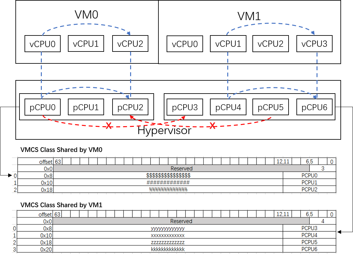
Figure 1 Virtual IPI issuing